New heights for new materials

In developing advanced tools for machining aerospace components, sometimes all you need is a simple microscope to understand how a material interacts with the cutting tool.
Advances in the aerospace industry are often linked to advances in materials – specifically the strength-to-weight ratio and the temperature resistance of new materials.
The materials of choice these days for aerospace engines are heat-resistant super alloys, or HRSAs, a complex cocktail of specialty metals – nickel, cobalt, iron and some TiAl (titanium aluminide)-based alloys – that provide crucial advantages such as allowing high working temperatures. Many of these components have complex forms and can be 3D-printed. That in turn creates new manufacturing opportunities and challenges for machine tool manufacturers such as Sandvik Coromant.
Trick in designing tools
Since the beginning of manned flight using airplanes made of wood and fabric, the name of the game for manufacturers has been to lower the weight of the aircraft. Over the years, aluminum and titanium alloy constructions replaced the wood and fabric, and eventually carbon fiber and composites entered the mix.
Compared with standard materials such as iron, today’s HRSA materials, in all their chemical and physical permutations, have fickle properties. More advanced tools are required to cut and finish aerospace components in batches that make financial and engineering sense for manufacturers.
The aerospace industry requires extremely high component tolerances
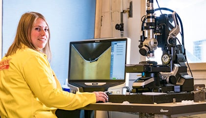
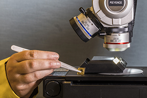
 Checking wear under the microscope.
“The trick in designing cutting tools has always been to increase the tool life by decreasing wear, while at the same time achieving higher cutting speeds,” says Stina Odelros, Senior R&D Engineer at Sandvik Coromant. “But the aerospace industry requires extremely high component tolerances, and sometimes there is no opportunity for a tool change in a process, so we are constantly developing new tools that perform better. We need to know what our customers struggle with, and then we try to solve their problems.”
Constantly tweaking materials
Odelros explains that airplane manufacturers and suppliers are constantly tweaking materials such as HRSA and other alloy mixes to achieve these goals. Besides the weight constraints, an engine component also needs to be able to withstand outside air temperatures as low as minus 60 degrees Celsius as well as internal engine temperatures of some 2,000 degrees Celsius.
Developing tools for this demanding industry is tricky. The only method to see how a tool is functioning is to look at the used inserts under a microscope to see how they wear. “We can’t access all of these materials on the market, so we depend on collaborations with key customers to tell us how our inserts are doing,” says Odelros.
Crux of the R&D work
As Odelros explains it, a 3D-printed, forged or cast airplane component cannot be lathed, milled, finished or drilled with a previously used tool. Sometimes machining a large and expensive engine component can take a week or two, and each machining pass must be continuous to avoid any structural deficiency. A tool breakdown halfway through this process is not acceptable as it could lead to a part failure. And a part failure in an engine could be catastrophic if it occurred in midair.
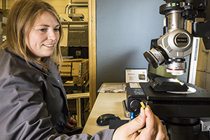
 Senior R&D Engineer Stina Odelros.
What Odelros looks for under the microscope then, besides controlled wear and tear, is the size of the wear and if more unpredictable types of wear such as chipping or fracture are present, which in a worst-case scenario could lead to costly production failures.
This is the crux of the R&D work. While a carbide insert is no bigger than an average fingernail, the permutations of its construction – the angles, substrates, coatings, material constitution, crystalline structure and treatments such as chemical or physical vapor deposition – are almost infinite. The right combination and mix can yield tailored results for specific customer uses.